CONTACT NUMBER:
15032073555
CONTACT NUMBER:
15032073555
The structure of the foam equipment should be able to ensure the establishment of a sufficiently high turbulent foam suspension layer, and at the same time, the flow resistance should be as low as possible to achieve high efficiency. The height and turbulence of the foam layer affect the operating strength of the equipment, that is to say the processing capacity of the equipment per unit volume. Flow resistance affects the energy consumed by the operation.
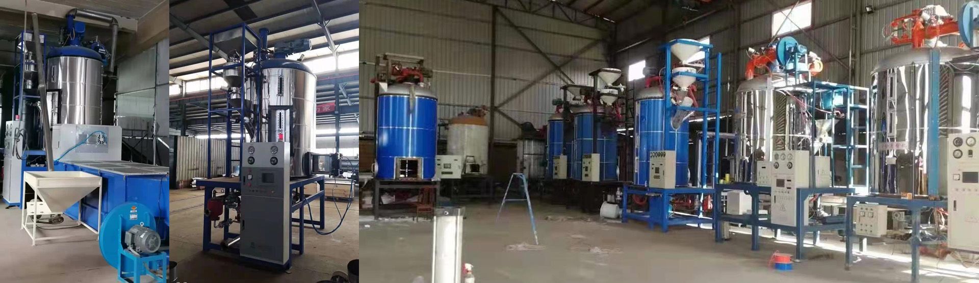
There are two types of foam equipment: single-board and multi-board. For dust-removing foam equipment, single-board is enough, so only single-board foam dust removal equipment is introduced here, and its dust removal efficiency can reach 99%.
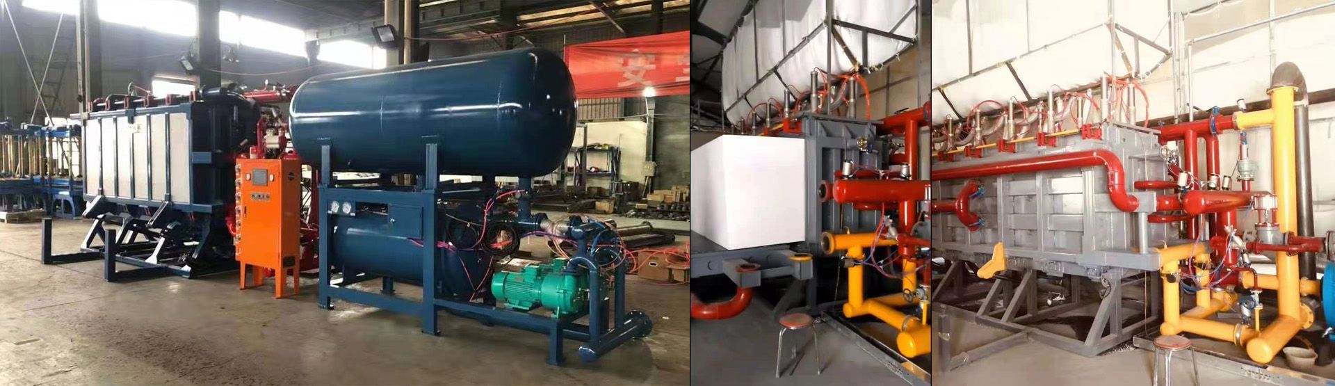
Shell structure single-plate foam dust removal equipment is a rectangular or circular cross-section container (shell), which is separated by a horizontal sieve plate. The shape of the sieve plate depends on the process requirements. When used as a dust collector, the lower part of the sieve plate Made into a conical or pyramidal funnel.
Compared with the rectangular cross-section, the circular cross-section can ensure more uniform gas distribution, and the shell has better pressure-bearing capacity under pressure or negative pressure, while the rectangular cross-section can ensure the liquid is more evenly distributed along the sieve plate. For the foam equipment for dust removal, because the gas volume is much larger than the liquid volume, and it is generally operated under normal pressure, it is more advantageous to use a rectangular cross section.
The maximum cross-sectional size of the equipment depends on the possibility of uniform gas distribution. For single-plate equipment, the optimum length along the liquid flow direction is 1.5~2.0m, not more than 2.5m. For larger-sized equipment, it is best to use a dual-flow sieve plate that introduces or discharges liquid in the middle of the sieve plate. If the gas processing capacity is large, the section of the equipment is also large. At this time, the gas distribution device before the gas enters the sieve plate should be considered.
The cross section of the tower can be calculated from the gas velocity of the empty tower. It was pointed out that the gas velocity of the empty tower is within the range of 1~3m/s. What kind of value should be used in the design? It depends on the specific conditions of the processing gas.
Copyright © Xinji Golden Phoenix Industrial and Trade Co, Ltd.